Science
Related: About this forumFaradaic electro-swing reactive adsorption for CO2 capture.
The paper I'll discuss in this post is this one: Faradaic electro-swing reactive adsorption for CO2 capture (Sahag Voskian and T. Alan Hatton Energy Environ. Sci., 2019, Advance Article Accessed 10/30/19).
I came across reference to this paper, out of MIT, in the scientific popular press, actually in several places, and since the quality of journalism describing science is often quite bad, decided to access the original paper.
The paper is, happily open sourced, and anyone can read it. I'll excerpt in offer the graphics in any case.
I've spent a lot of time reading about separations of carbon dioxide from various matrices and I will say that this one is somewhat unique, an electrochemical approach. Since the separation of carbon dioxide, a low energy gas, from dilute matrices requires overcoming entropy, this process is not energy neutral by any means; it costs energy, but it may be more efficient. It does not seem operative at air concentrations of CO2, requiring concentrations of 0.6% as compared to 0.041% in air (as of this writing).
The system uses a rather well known organic redox system, dibenzoquinones/dibenzoyhydroquinone in a very creative way
From the introductory text:
In addition to the capture of CO2 from direct combustion processes, there is a need to remove CO2 from enclosed spaces for ventilation purposes in buildings and car cabins, or for cabin environmental control systems on board spacecraft and submarines, where the maximum allowed CO2 concentration in habitable spaces is 5000 ppm (or 0.5%).10 The first of such systems was developed by Winnick et al., for the electrochemical capture of CO2 in spacecraft cabins using molten carbonates.11 However, the low concentration of CO2 in such applications poses a challenge, mainly due to the low driving forces for mass transfer and the large quantities of other species present in air in addition to CO2.12 Thus, carbon capture is a multi-scale problem, where the CO2-rich streams to be treated vary greatly in volume, concentration and composition, and different criteria need to be fulfilled to ensure optimal processing depending on whether sources are industrial or small-scale (e.g., power plants or oil and gas heaters), concentrated or dilute (exhausts from combustion or air in confined spaces), and clean or contaminated with other pollutants.
Many of the CO2-capture chemical processes that involve a capture agent such as amines or solid sorbents require temperature and/or pressure swings to release the captured CO2 and regenerate the agents for further capture. These swings result in inefficiencies due to energy wasted in heating solvents and sorbents, pressurizing feed gas, or drawing a vacuum for desorption. Electrochemical systems can minimize such parasitic energy losses as they can be operated at near isothermal conditions, with significantly higher efficiencies than their thermal-swing (TSA) and pressure-swing (PSA) adsorption counterparts.13 One mode of electrochemical capture of CO2 is through the use of a redox-active carrier.
Electrochemically mediated selective transport of chemical species was first reported by Ward et al.,14 where a redox-active carrier (ferrous ion) was used to transport nitric oxide across a membrane. Since then, a number of systems have been developed for transporting chemical species by redox-active carriers that are activated at one electrode, to bind with the target species, and deactivated at the opposite electrode, to release the target and regenerate the carrier.15,16 Systems that have been proposed for the concentration of CO2 through this approach have been based on a number of different carrier molecules, such as quinones,17–20 4,4?-bipyridine,21 and thiolates.22,23 Quinones are of particular interest to this work for their superior electrochemical performance, serving as redox-active carriers for CO2 in electrochemically mediated separation processes. DuBois et al. demonstrated this possibility, and studied the thermodynamics of an electrochemical CO2 pumping system that utilizes quinones.18 More work followed, where Scovazzo et al. demonstrated the electrochemical separation of CO2 from <1% concentration gas mixtures using 2,6-di-tert-butyl-1,4-benzoquinone as a carrier in ionic liquid (IL) and organic solvent electrolytes media,19 while Gurkan et al. screened a number of ILs to serve as suitable electrolytes for quinone carriers in an electrochemically mediated selective transport system for CO2.20 All of these systems, however, require the transport of the electrolyte and the dissolved carrier molecules between two electrodes in an electrochemical cell for capture and release of CO2. This limits their implementation in a number of applications where the requirement for flow systems and pumping, and the large footprint, are problematic.
The quinones are oxidized and reduced by a porous matrix carbon nanotube (CNT) supported ferrocene polymer.
This nice graphic cartoon shows the systems operation.
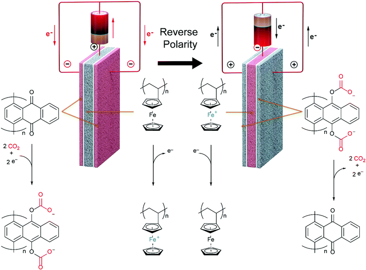
The caption:
This system is designed to treat flue gases, but may be adapted to other types of systems. Recently I've been thinking quite a bit about carbon dioxide as a working fluid for Brayton type devices, and in particular have been focusing attention on a cycle with which I was not familiar until recently, the Allam cycle.
It is a closed cycle, where the combustion gas is also the working fluid.
The Allam cycle is designed primarily for use with dangerous natural gas, but I would imagine that it could also be adapted to other systems, notably those derived from biomass.
During the Allam cycle, portions of the carbon dioxide working fluid are removed from the system, commonly described as being for the purpose of "storage," but coupled with nuclear primary energy, could be utilized for the purpose of making materials, for example carbon nanotubes impregnated with, um, ferrocene polymers, and millions of other similar products.
Anyway, from the paper, some SEM images of the system:
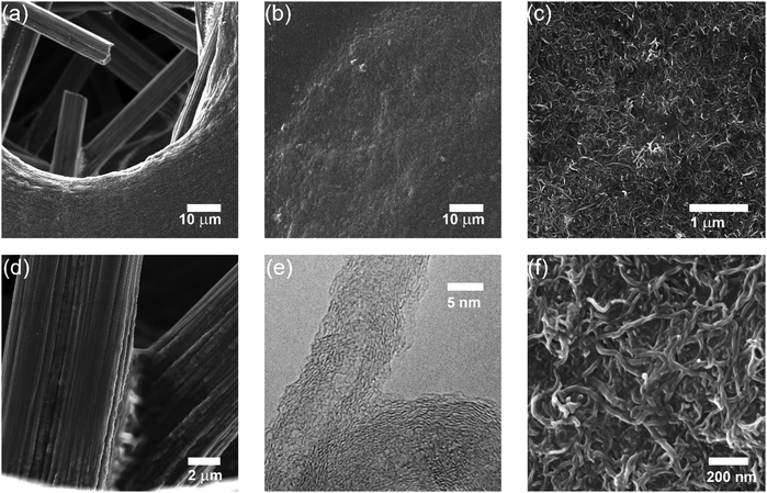
The "? ?" here is reference to the interaction between the aromatic rings of the benzoquinones and those of the carbon nanotubes.
Cyclic voltamograms of the reduction system:
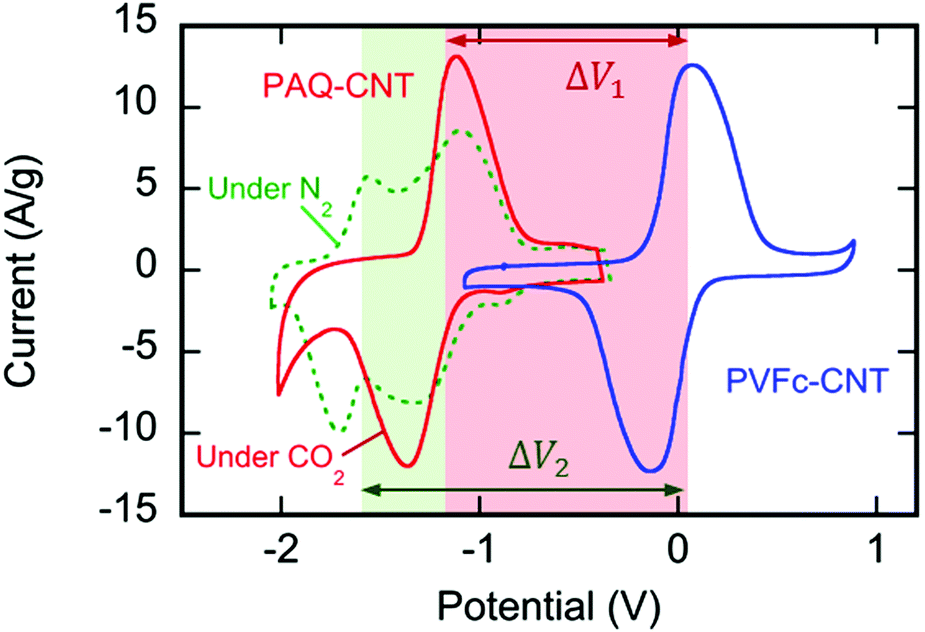
(It is worth noting that increasingly more electrochemical reduction systems for carbon dioxide are known.)
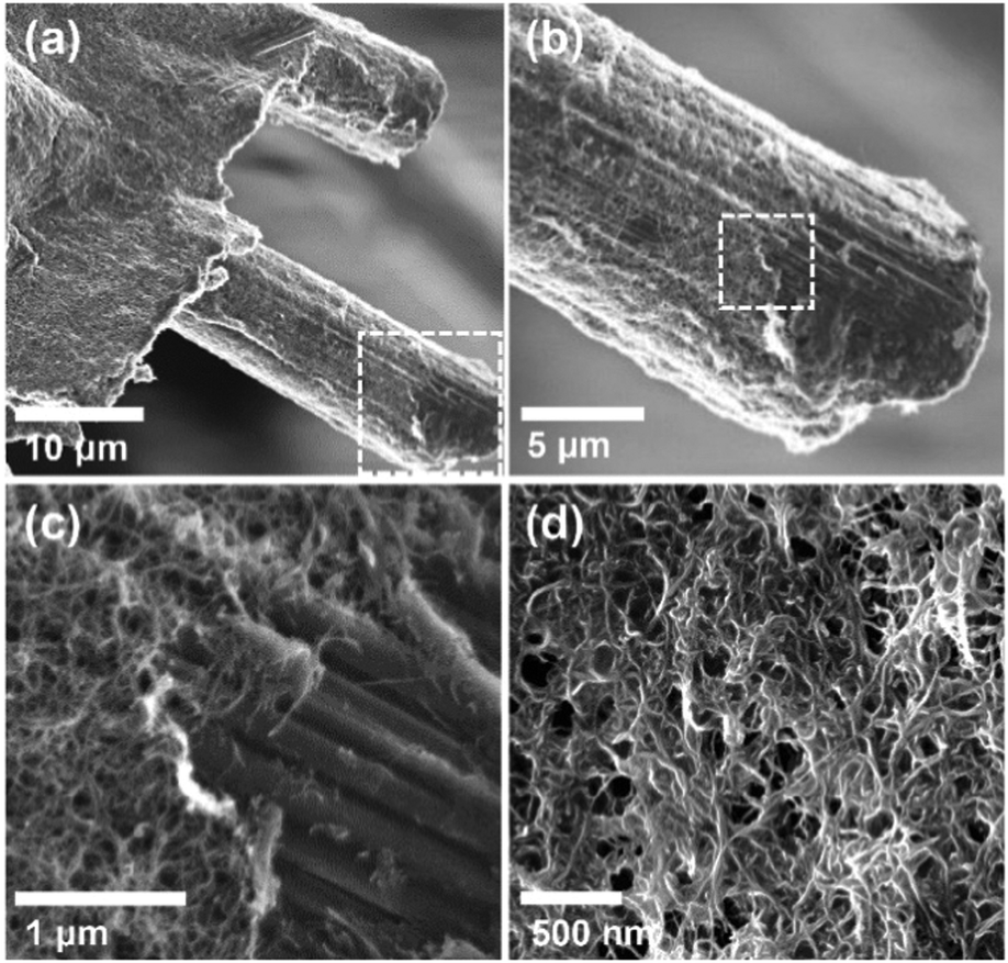
More SEM images:
Nice photographs of the experimental apparatus:
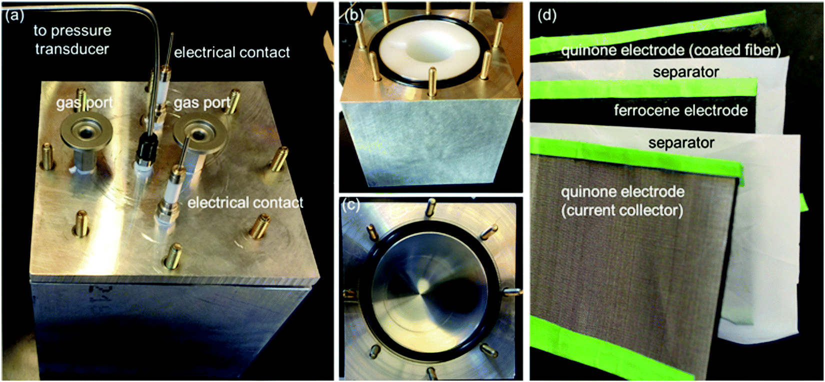
They obviously have a nice machine shop at MIT.
The system shows nice stability over a large number of cycles:
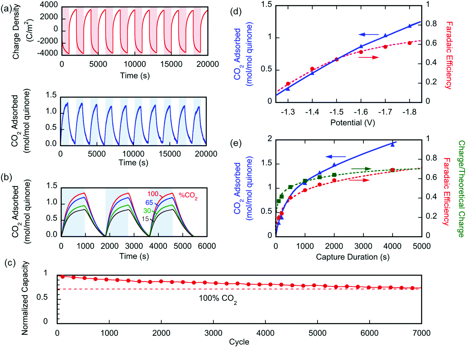
Fig. 6 (a) Changes in the number of moles of CO2 captured upon charging and discharge of the electrochemical cell over 10 cycles, normalized by the moles of quinone on the electrode ( ). The CO2 captured from and released to the chamber tracks the charge applied to the electrochemical cell, normalized by the area of the cell ( ). (b) The CO2 captured under different feed concentrations. (c) Capacity of cell over 7000 cycles. In a different set of experiments using a larger cell and cavity, (d) shows the effect of varying charging potential for a 1000 s capture and (e) shows the effect of varying the capture duration at ?1.8 V capture potential. These experiments were conducted at T ? 21 °C.
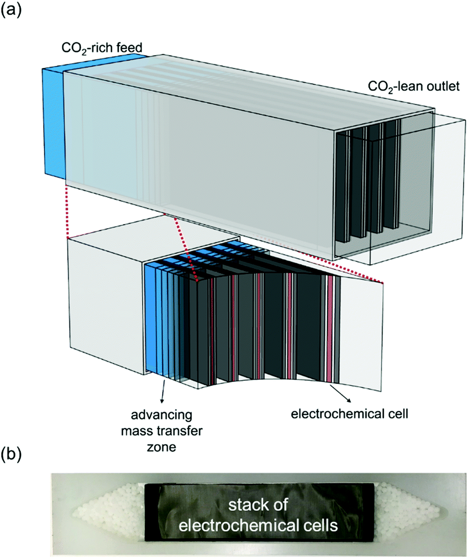
A cartoon of the configuration of the system:
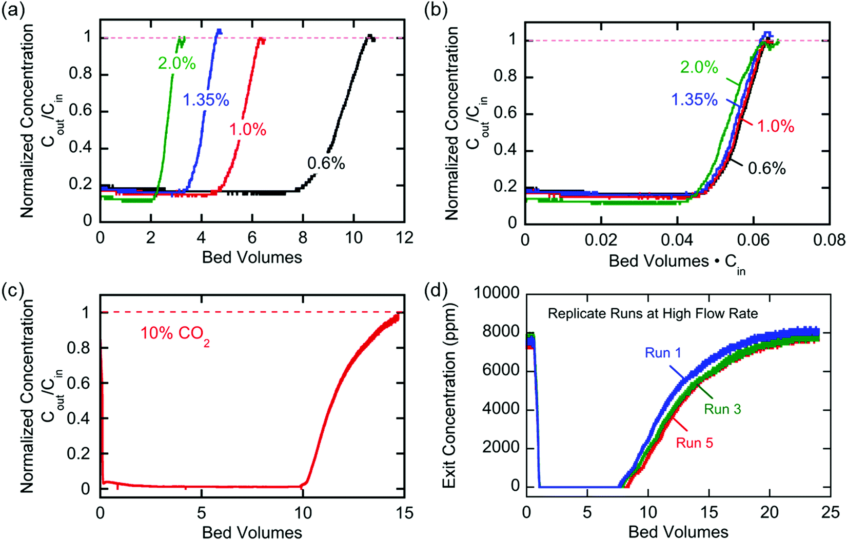
Breakthrough at various concentrations:
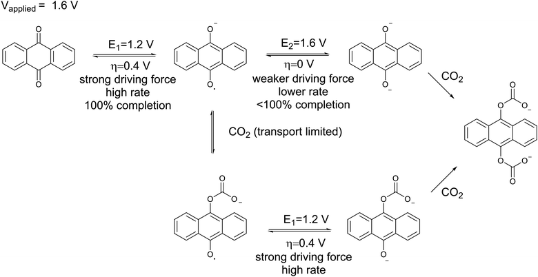
A chemical schematic of the process:
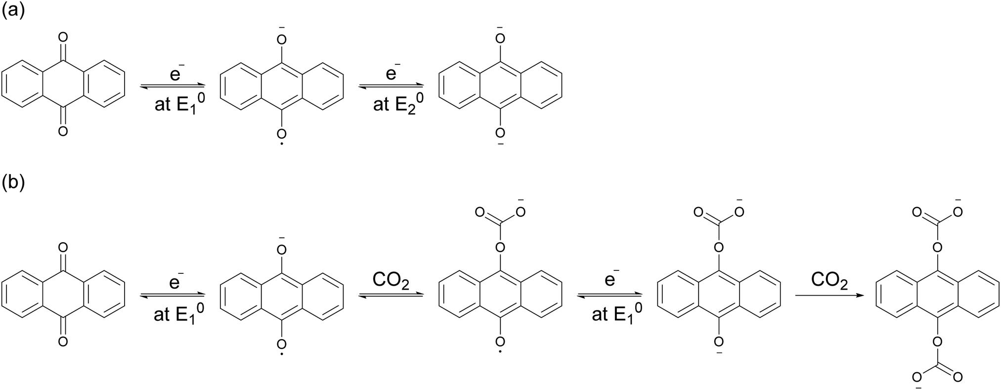
The electrochemical reaction scheme:

A cartoon of the electrochemical cell configuration:
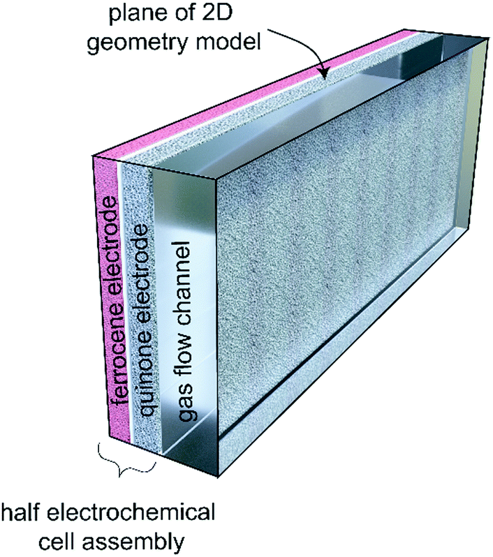
A graphic of charge and discharge of the system:
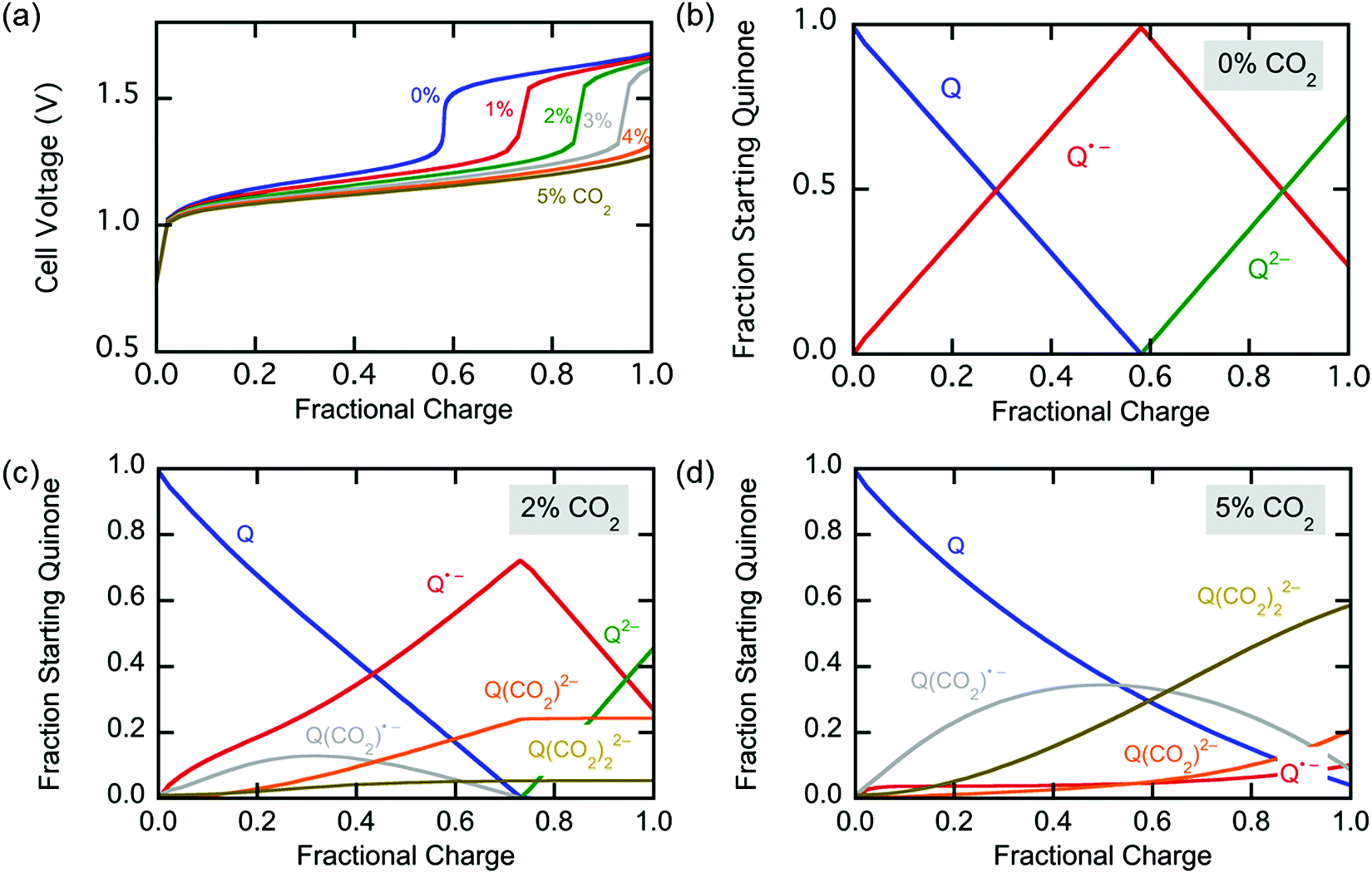
More on breakthrough (the physical saturation of the system):
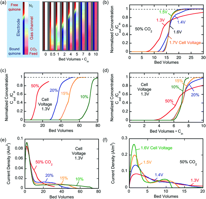
More electrochemical schematics:
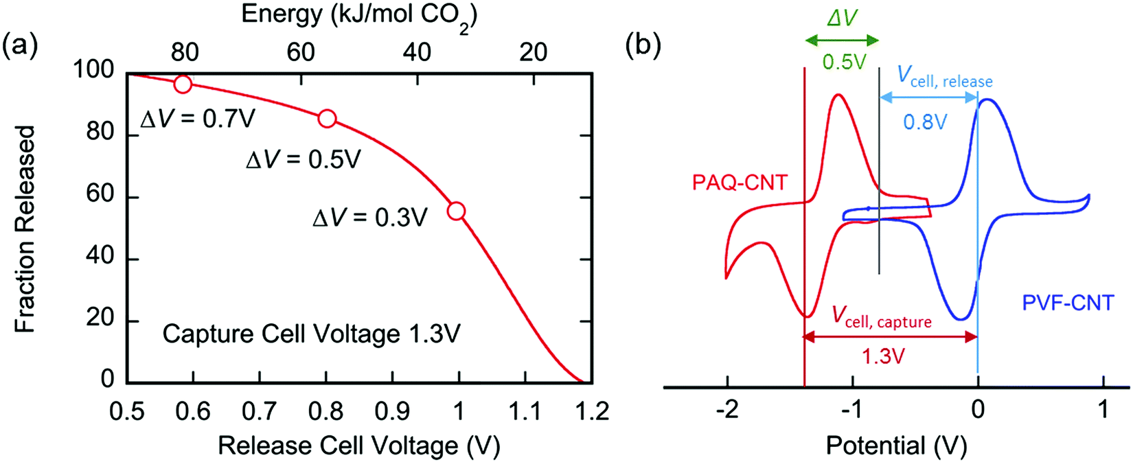
An important graphic showing the energy penalties associated with carbon capture using this device:
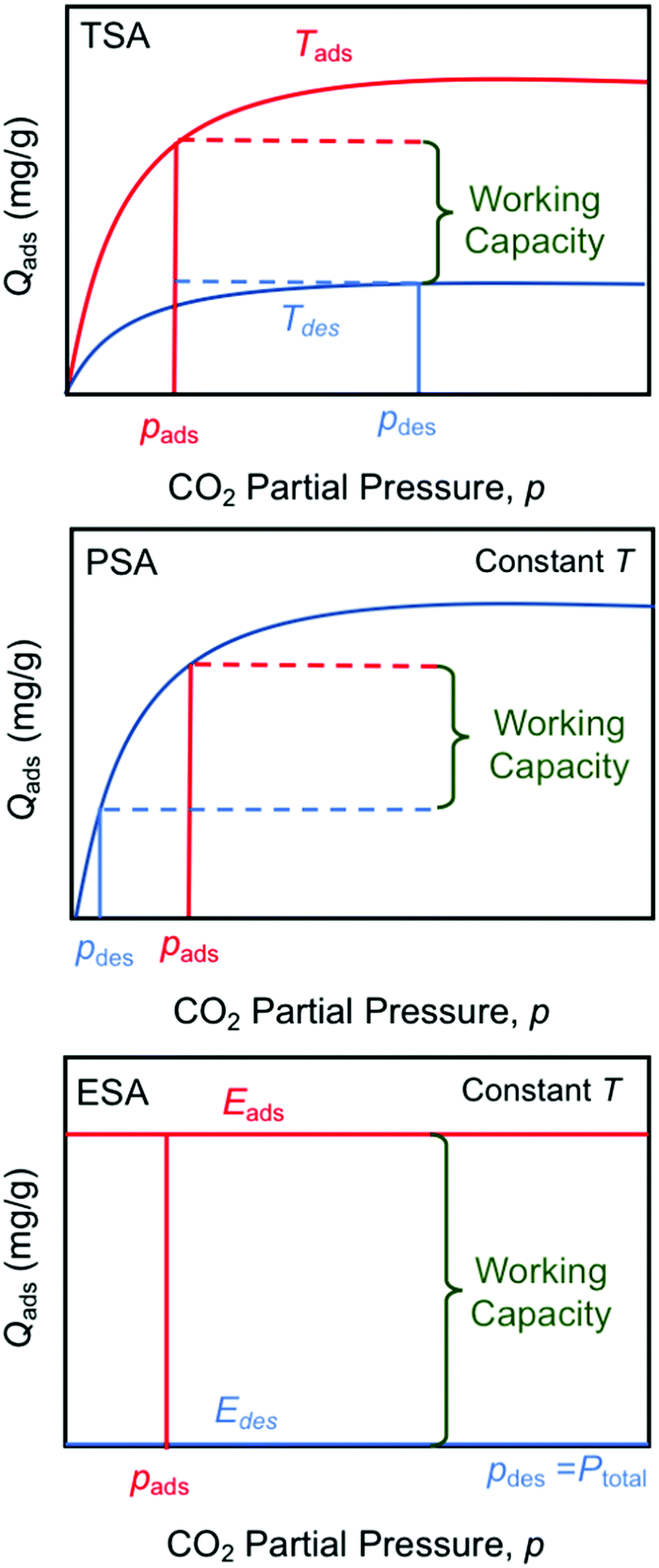
There are several types of "swing" approaches to gas separations commonly used, "temperature swing" - a simple well known example is to use a metal hydroxide, calcium hydroxide ("slaked lime"
They are compared in this graphic:
I note that electricity is always produced at a thermodynamic loss, and thus electricity can, and often is, thermodynamically questionable. Irrespective of popular opinion to the contrary, electricity is not "green" or "clean."
However, there are circumstances where it can be utilized as a thermodynamic enhancer, specifically at very high temperatures, where it is a side product of another process. For example, the thermochemical splitting of water (or carbon dioxide) can be driven at high temperatures with far greater thermodynamic efficiency than via electrochemical approaches, most famously used for water electrolysis. Since the hydrogen and oxygen in the thermochemical water case, and carbon monoxide and oxygen in the carbon dioxide thermochemical case, will ultimately be brought to ambient temperatures, a temperature gradient is necessary, and as such can be utilized to drive turbines (Brayton), boil water (Rankine) or both, raising the efficiency.
Such temperatures are only economically, thermodynamically and environmentally viable with nuclear energy.
Cool idea; cool paper.
Have a nice day tomorrow.
erronis
(15,216 posts)However "Such temperatures are only economically, thermodynamically and environmentally viable with nuclear energy" (Your opinion, right?)
This seems like a personal value judgement. Not one that I disagree with, but maybe subject to discussion.
I worked for US/French nuclear fission reactor companies for several years in the 80s and 90s. Unless significant advances have been made in waste disposal recently, I still question the "environmentally viable" clause.
As an aside, if fusion-based generators become a reality, how will this change these equations?